

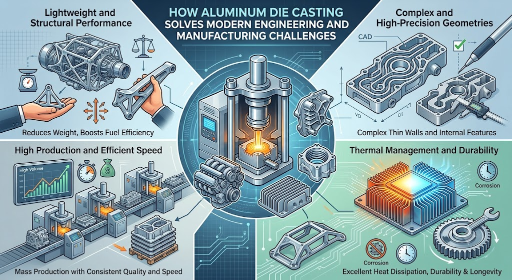
Aluminum die casting gives engineers a fast way to produce light, detailed, and repeatable metal parts. The process forces molten aluminum alloy into a reusable steel die under high pressure. The metal fills the cavity, cools, and forms a part that closely matches the designed shape.
Manufacturers use this process for housings, brackets, heat sinks, covers, tool bodies, and structural components. It can combine several functions in one part. It can also reduce assembly work and support stable production at scale. These benefits make the process useful in automotive, marine, lighting, electronics, medical equipment, and general industrial projects.
The method does not solve every production problem. Steel tooling costs more than simple prototype tooling. Poor part design can create trapped gas, incomplete filling, distortion, or early tool wear. Engineers must connect product design, die design, process control, machining, finishing, and inspection from the start.
Why Engineers Choose Aluminum Die Casting
The production cycle starts with a steel die that contains the shape of the part. A machine closes the die and injects molten alloy into its cavity. The metal cools while the die controls its form. Ejector pins release the solid casting, and a trimming step removes gates, runners, and flash.
Aluminum normally uses a cold-chamber die-casting machine. A separate furnace melts the alloy. A ladle or automated dosing system transfers a measured amount of metal into the shot chamber. A plunger then forces the metal into the closed die. This arrangement protects the injection system from long contact with molten aluminum.
Engineers often select aluminum because it combines low weight with useful mechanical strength. The material also offers good corrosion resistance, dimensional stability, and thermal and electrical conductivity. Common die-casting alloys include A360, A380, and A383. Each alloy provides a different balance of fluidity, strength, corrosion resistance, and machining behavior.
Aluminum die casting can form thin walls, ribs, bosses, mounting points, and internal passages in one production step. A designer can replace a group of stamped, machined, or assembled pieces with one casting. This choice can reduce fasteners, assembly time, and the number of items that a factory must purchase and track.
Production volume plays a major role in the decision. A steel die needs a significant initial investment. The same die can then produce many repeatable parts with short cycles. The unit cost often becomes more competitive as the order volume rises. A small prototype order may fit CNC machining, sand casting, or another low-tooling method better.
The process also provides a useful surface for many products. Some castings need only trimming and light cleaning. Other parts receive shot blasting, polishing, powder coating, paint, chromate conversion, or another finish. The final choice depends on corrosion exposure, appearance, wear, electrical contact, and cost.
How Part and Die Design Shape the Result
A die-cast part starts with the product drawing, but the drawing must support metal flow and controlled cooling. Uniform walls help the alloy move through the cavity and cool at a similar rate. Large changes in thickness can create hot areas, shrinkage, or distortion. Engineers often use ribs instead of thick solid sections when a part needs more stiffness.
Draft angles help the casting leave the die. A vertical wall without enough draft can drag against the tool during ejection. This contact can damage the surface, increase ejector force, and slow production. The required angle depends on wall depth, surface texture, alloy, and tool design.
Rounded corners also improve the result. Sharp internal corners can restrict flow and raise local stress. A suitable radius lets the metal fill the area more smoothly. It also reduces stress in the finished part and can extend die life.
The parting line marks the place where the main die halves meet. Its position affects flash, appearance, trimming, and dimensional control. Designers should keep the parting line away from sealing faces and other critical surfaces when possible. Side openings may require slides or movable cores, which add tool cost and maintenance needs.
The die contains a full metal-delivery system. Runners carry molten alloy from the shot chamber. Gates control where and how quickly the metal enters the cavity. Vents let air escape. Overflows collect early or cooler metal. Cooling channels control die temperature, while ejector pins release the solid part.
Engineers can use flow simulation before they cut the tool. The software can show the expected fill pattern, air traps, cold areas, and uneven solidification. The team can then change a gate, vent, overflow, or wall before tool construction. Simulation cannot replace sample testing, but it can reduce avoidable tool changes.
Early supplier review often saves time. The product engineer knows the part function. The tool engineer understands flow, cooling, and ejection. The machining team sees where cutters and fixtures need access. A joint review can find conflicts before they become expensive production problems.
Common Casting Defects and Practical Solutions
Every casting process has risks. The goal is not to inspect quality into a finished batch. The goal is to control the causes during design and production. A clear control plan links each known risk with a prevention method and a suitable test.
| Production issue | Common cause | Practical response |
| Gas porosity | Trapped air, poor venting, or unstable injection | Improve vents and overflows, control shot settings, use vacuum support, and inspect critical zones |
| Incomplete filling | Low metal temperature, weak flow, thin sections, or poor gate position | Adjust temperature and speed, improve gate design, and revise difficult wall sections |
| Shrinkage porosity | Uneven cooling or heavy local sections | Use more uniform walls, improve cooling, and move heavy sections away from critical areas |
| Flash | Die wear, weak clamping, or incorrect process pressure | Maintain the die, verify clamping force, and control injection pressure |
| Distortion | Uneven cooling, early ejection, or weak geometry | Balance cooling, adjust cycle time, add ribs, and improve part support during handling |
| Surface defects | Poor metal flow, die residue, or weak surface preparation | Stabilize casting conditions, clean the die, and prepare the part before finishing |
Gas porosity is a common concern in high-pressure production because the alloy enters the cavity at high speed. Air can remain inside the metal if the die cannot release it. Engineers can improve venting, use vacuum systems, tune the shot profile, and avoid wall shapes that trap flow. High-vacuum and squeeze processes can support parts that need higher integrity.
Porosity does not affect every part in the same way. A small internal void may have little effect in a decorative cover. The same void can cause a leak in a pump housing or appear during machining of a sealing face. The team must place quality limits according to part function rather than apply one rule to every casting.
Incomplete filling happens when the metal begins to solidify before it reaches the full cavity. Very thin walls, long flow paths, low temperatures, or a weak gate position can raise this risk. The response may involve process changes, but some parts need a design change. A slightly wider flow path can solve a problem that machine pressure alone cannot fix.
Flash forms when metal enters the small gap between die sections. Some flash is normal and leaves during trimming. Heavy or changing flash can point to die wear, poor alignment, weak clamping, or incorrect settings. Regular tool maintenance prevents a small issue from growing into high scrap rates.
How Automation and Quality Control Improve Production
Automation helps a factory repeat the same production steps. Automated ladles or dosing systems can control the amount of molten alloy in each shot. Robots can spray release agent, remove hot castings, trim gates, and transfer parts to cooling or inspection stations. Sensors can record metal temperature, die temperature, pressure, injection speed, and cycle time.
Process data becomes useful when the team connects it with part results. A temperature value alone does not prove quality. Engineers must define safe process limits and study what happens when a value moves. A stable record can show a slow change before it creates a large batch of rejected parts.
CNC machining completes features that aluminum die casting cannot finish alone. A machining center can cut threads, valve bores, bearing seats, sealing faces, and precise mounting holes. The designer should limit machining to functional areas because each cut adds time, fixtures, tools, inspection, and scrap risk.
Fixture design affects machining quality. The fixture must locate each casting from stable reference points. It must hold the part without bending a thin wall. It also must allow small casting variations while keeping the machined feature in the correct position.
Dimensional inspection can use gauges, calipers, coordinate measuring machines, and 3D scanners. A coordinate measuring machine checks defined points and geometric tolerances. A scanner compares a wide surface with the digital model. Material spectrometry can confirm alloy chemistry, while surface-roughness equipment can check machined or finished zones.
Pressure-tight parts may need leak testing. X-ray inspection can reveal some internal voids without cutting the part. Salt-spray testing can support checks of corrosion-protection systems. Destructive sectioning can help engineers study internal structure during process validation. The correct test set depends on the risks of the product.
First article inspection gives the customer evidence before full production. The report can include measured dimensions, alloy records, process information, finish results, and photographs. Later inspections confirm that the approved process remains stable. Traceability connects each shipment with its material batch, production date, machine, tool, and inspection records.
Where Aluminum Die Casting Delivers Real Value
Automotive engineers use cast aluminum for covers, brackets, housings, thermal parts, and some structural components. Low mass helps vehicle designers control total weight. Repeatable tooling supports large production programs, while cast ribs and mounting points can reduce later assembly work.
Pneumatic tool bodies show how one casting can perform several jobs. The outer shell provides a grip and protects internal parts. Cast ribs add stiffness. Internal passages can guide air, while machined ports and bores hold valves and fittings. Paint or powder coating protects the surface and carries the product color.
Marine housings face water, salt, vibration, and impact. A lower-unit housing for an outboard motor needs an accurate shape, machined interfaces, and suitable corrosion protection. One active supplier catalog lists such housings in ADC-3 or A360 alloy with chromate conversion. The same catalog lists pneumatic tool housings in ADC-12 or A383 with paint or powder coating. These examples show how alloy, machining, and finish change with the operating environment.
LED lighting uses aluminum housings and heat sinks because aluminum transfers heat away from electronic components. A casting can combine fins, mounting points, cable entries, and protective walls. The engineer still must check metal flow around thin fins and maintain a clear thermal path from the circuit board to the outside air.
Electronics manufacturers use the process for controller cases, motor housings, and power-system enclosures. A metal enclosure can protect components, support heat transfer, and provide electromagnetic shielding. Machined faces may hold seals, connectors, or covers. A coating can add corrosion protection, but contact areas may need masking to keep electrical continuity.
Medical equipment can use cast parts in lighting systems, equipment arms, pump structures, and diagnostic machines. These projects may need accurate dimensions, cleanable finishes, traceable records, and strict change control. The casting process must support the requirements of the final device, but it does not replace product-level testing or regulatory approval.
How Engineers Can Decide If the Process Fits a Project
The first question concerns production volume. A reusable steel die needs enough parts to justify its cost. Engineers should compare total program cost rather than compare only the price of one casting. The review should include tooling, samples, machining, finishing, inspection, assembly, scrap, packaging, and expected tool maintenance.
The second question concerns geometry. Aluminum die casting works well for detailed shapes, thin walls, ribs, bosses, and integrated mounting features. The part still needs suitable draft, radii, parting lines, and metal-flow paths. Deep side features can require slides and raise tool cost.
The third question concerns performance. The team must define loads, temperature, corrosion exposure, pressure tightness, surface needs, and service life. These requirements guide alloy choice, casting method, heat treatment options, machining, finish, and testing. A pressure housing needs a different process plan from a simple cover.
Supplier capability also matters. Buyers should review die-design experience, machine range, alloy control, machining capacity, finishing partners, inspection equipment, quality systems, traceability, capacity, and communication. A low quote offers little value if the supplier cannot hold a critical bore or control leakage.
Aluminum die casting works best when engineers treat it as a connected production system. Product design affects die design. Die design affects flow and cooling. Casting quality affects machining and finishing. Inspection confirms the result, but early engineering choices create it. A team that connects these stages can produce lighter parts, reduce assembly work, and maintain stable output across long production runs.
